Session 3: Motors and Movement
Goal: Connect a yellow DC motor to the micro:bit using an L298N motor driver and learn to control speed and direction — the first step toward building a moving robot!
📺 Watch First
Before we start wiring, watch this short video that walks through connecting a motor to a micro:bit with an L298N driver:
▶ Motor Driver + micro:bit Tutorial
Follow along — we’ll be doing the same setup in class!
What Are We Building?
By the end of this session you will have one motor wired up and controllable from the micro:bit. You’ll write forward, backward, and stop functions — the building blocks of any robot.
Meet Your Components
Yellow TT DC Motor
The yellow “TT” (transparent tire) gear motor is the workhorse of hobby robotics:
- Operating voltage: 3 V – 6 V (we’ll use ~5–6 V from a battery pack)
- Built-in gearbox that trades speed for torque — perfect for driving wheels
- Two solder tabs for power (no polarity marking — swapping the wires just reverses the direction)
L298N Motor Driver Board
The micro:bit’s pins can only supply a tiny amount of current. A motor can draw 100–200 mA — way too much! The L298N dual H-bridge driver sits between the micro:bit and the motor and does the heavy lifting.
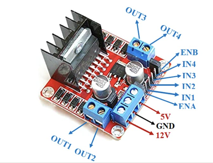
The key parts of the board we’ll use:
- OUT1 & OUT2 — connect your motor wires here
- +12V (VMS) — motor power input (battery pack positive)
- GND — common ground (battery negative and micro:bit GND)
- ENA — enable / speed control (PWM from micro:bit)
- IN1, IN2 — direction control pins
Key idea: IN1/IN2 set the direction; ENA sets the speed.
Wiring It Up
Components You’ll Need
- micro:bit + breakout board (edge connector)
- L298N motor driver module
- 1 × yellow TT DC motor (with wheel attached)
- 4 × AA battery holder (6 V)
- Jumper wires (male-to-female recommended)
- Small screwdriver for the L298N screw terminals
Pin Assignments
The micro:bit has three large pins you can easily connect with alligator clips or a breakout board: Pin 0, Pin 1, and Pin 2. We’ll use them like this:
- Pin 0 → ENA (speed control — PWM)
- Pin 1 → IN1 (direction control)
- Pin 2 → IN2 (direction control)
Step-by-Step Wiring
⚠️ Keep the battery pack switched OFF (or disconnected) while wiring!
-
Remove the ENA jumper cap on the L298N board — we will control speed with PWM from the micro:bit instead of running at full speed.
-
Connect the motor
- Loosen the screw terminals on OUT1/OUT2 and insert the two wires from the motor. Tighten.
-
Connect power
- Battery pack positive (+) → L298N +12V terminal.
- Battery pack negative (–) → L298N GND terminal.
- Run a wire from L298N GND to the micro:bit GND pin (common ground is essential!).
-
Connect control pins (micro:bit → L298N)
- Pin 0 → ENA (speed)
- Pin 1 → IN1 (direction)
- Pin 2 → IN2 (direction)
-
Double-check every connection with your partner, then have the teacher verify before powering on.
How Motor Direction Works
The L298N uses two input pins to set direction:
- IN1 = HIGH, IN2 = LOW → Motor spins forward
- IN1 = LOW, IN2 = HIGH → Motor spins backward
- IN1 = LOW, IN2 = LOW → Motor stops (coast)
The ENA pin controls speed using PWM — a value from 0 (stopped) to 1023 (full speed).
Programming the Motor
Activity 1: Make the Motor Spin
In MakeCode — open a new project.
On button A pressed:
- From Pins (under Advanced), add
digital write pin P1 to 1 - Add
digital write pin P2 to 0 - Add
analog write pin P0 to 600
This sets the motor to spin forward at moderate speed.
On button B pressed:
digital write pin P1 to 0digital write pin P2 to 0analog write pin P0 to 0
This stops the motor.
Test it! Press A — the motor should spin. Press B — it stops.
Troubleshooting: If the motor doesn’t turn, check:
- Is the battery pack switched on?
- Is GND shared between battery, L298N, and micro:bit?
- Did you remove the ENA jumper cap?
- Are IN1/IN2 connected to P1/P2 (not swapped)?
Activity 2: Create Forward, Backward, and Stop Functions
In MakeCode, go to Advanced → Functions → Make a Function. We’ll create three functions:
Function: forward
digital write pin P1 to 1digital write pin P2 to 0analog write pin P0 to 700show arrow North(up arrow on LEDs)
Function: backward
digital write pin P1 to 0digital write pin P2 to 1analog write pin P0 to 700show arrow South(down arrow on LEDs)
Function: stop
digital write pin P1 to 0digital write pin P2 to 0analog write pin P0 to 0show icon X(stop symbol on LEDs)
Now call the functions from a forever loop to make the motor run a repeating pattern automatically:
In the forever block:
- Call
forward pause 2000 ms(run forward for 2 seconds)- Call
stop pause 1000 ms(pause for 1 second)- Call
backward pause 2000 ms(run backward for 2 seconds)- Call
stop pause 1000 ms(pause for 1 second)
The motor will now repeat the sequence on its own — forward, stop, backward, stop — forever! This is exactly how a real robot would follow a programmed path.
Test it! Watch the LED arrows change as the motor changes direction.
🎯 Challenge: Design Your Own Motor Program
Your Task: Use the
forward,backward, andstopfunctions to create something interesting — you decide what it does!
Here are some ideas to get you thinking, but feel free to come up with your own:
- Dance pattern — a timed sequence of forward/backward/stop moves set to a beat using the Music blocks
- Morse code motor — use short and long motor bursts to “spell out” a letter or word
- Countdown launcher — count down from 5 on the LEDs, then run a sequence
- Sensor-triggered — combine what you learned in Session 2: use the IR sensor to decide when to run forward or stop
- Something totally different — surprise us!
There’s no single right answer. Experiment, break things, fix them, and have fun.
Key Concepts You Learned
- How a DC motor converts electricity into rotation
- Why we need a motor driver (the micro:bit can’t power motors directly)
- L298N wiring: direction pins (IN1/IN2 on P1/P2) and speed pin (ENA on P0)
- PWM (0–1023) to control motor speed like a dimmer switch
- Using functions to organize your code into reusable blocks
Think About It:
- What would you need to change to control two motors at once?
- How could you combine the IR sensor from Session 2 with a motor to make a robot that avoids obstacles?
- What other sensors could help a robot navigate?
Next Session Preview: We’ll add a second motor and mount everything onto a chassis to build a rolling robot! 🤖